Ignition Tuning
Viewing, editing, and knock-retarding the ignition timing table
The Ignition page displays your table ignition timing and allows automated adjustment based on logged knock data. Anywhere a knock event is detected in the logs, the timing is likely to be too advanced. The ignition timing table makes reductions at the location of the knock event, and decaying adjustments in surrounding cells to produce a smooth, knock-resistant timing map.
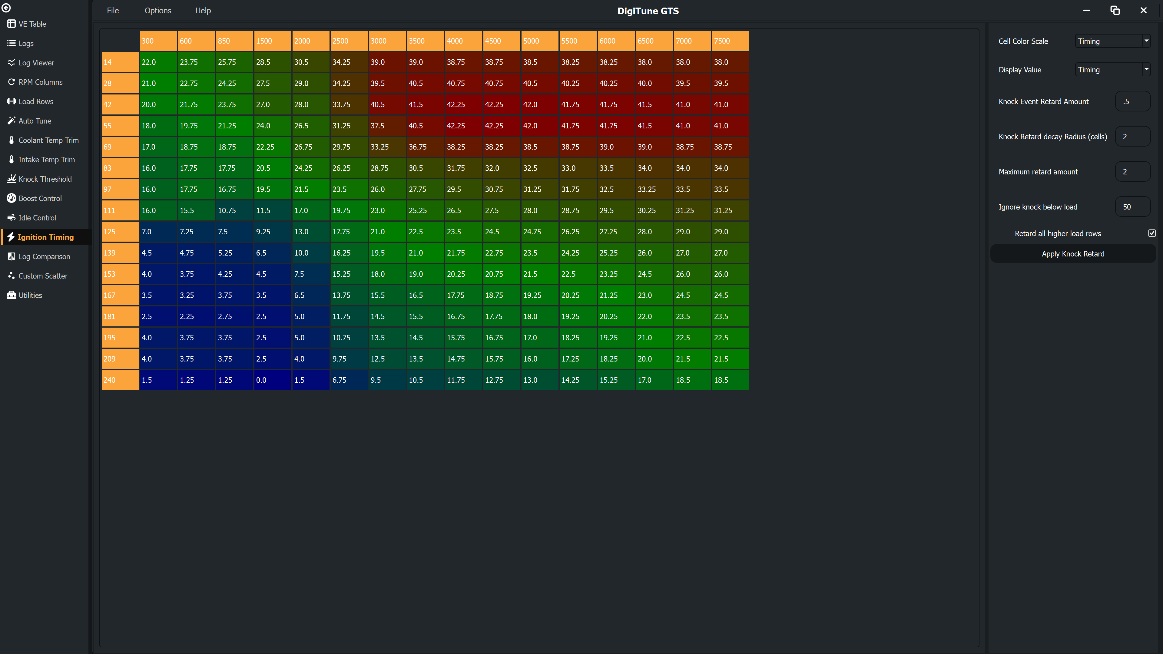
The timing table
The table displays your full ignition advance map with Load on the row axis and RPM on the column axis. Cells can be edited directly — select one or more cells and type a value, or use the keyboard shortcuts listed in Keyboard Shortcuts. All the same editing tools available on the fuel pages work here: increment/decrement, interpolate, set-value, copy and paste.
Click Update to commit pending changes to the in-memory calibration, or Reset to discard them.
Knock-based retard
When logs containing knock events are loaded, DigiTune GTS calculates a pending retard for each cell. This is the amount by which that cell's timing should be reduced to move it away from the knock threshold. Retard is strongest at the cell closest to where the knock occurred, then decays smoothly across neighbouring cells according to the Decay Radius.
Click Apply Retard to subtract the pending retard from the timing table. The pending retard values are kept after applying, so you can inspect them even after the correction has been made.
Controls
| Control | Default | Description |
|---|---|---|
| Retard Amount (°) | 0.5 | How many degrees to retard the timing at the exact cell where a knock event occurred. |
| Decay Radius (cells) | 2.0 | Radius over which the retard tapers to zero. A radius of 2 means a knock event at cell (r,c) also contributes retard to cells up to 2 steps away in any direction, with the amount falling off linearly with distance. |
| Max Retard (°) | 2.0 | Maximum retard that can accumulate in a single cell from one Apply operation. Prevents runaway correction when many knock events land in the same area. |
| Min Load (%) | 50 | Knock events below this load value are ignored. Low-load knock is often spurious (sensor noise, light pinging) and should not drive retard in cells that matter for performance. |
| Apply to Higher Loads | Off | When checked, for each RPM column the retard is propagated upwards so that no higher-load cell receives less retard than a lower-load cell in the same column. Useful when you want to ensure that knock at part-throttle drives at least equal retard at full throttle. |
Colour modes
The Colour Mode dropdown changes how cells are coloured:
- Timing — standard heatmap across the timing values in the table.
- Knock Events — cells are shaded by the amount of pending retard. Cells with the most retard appear darkest, making it easy to see which areas of the map were most affected by knock.
Value display
The Display dropdown switches the table between showing the timing values and showing the pending retard amounts. Switching to retard view lets you inspect the calculated correction before committing it with Apply Retard.
Recommended workflow
- Load logs that cover the RPM and load range you want to check.
- Open the Knock Tuning page to review where knock events occurred and verify the threshold table is set appropriately.
- Return to the Ignition page. Switch the Colour Mode to Knock Events to see which cells have pending retard.
- Switch the Display to Retard to review the magnitude of the calculated corrections cell-by-cell.
- Adjust Retard Amount, Decay Radius, and Max Retard until the corrections look sensible.
- Click Apply Retard. The timing values are updated immediately.
- Save the map and load it to the ECU, then collect a validation log to confirm knock events have been resolved.