Knock Tuning
Setting knock acceptable level thresholds by RPM and load
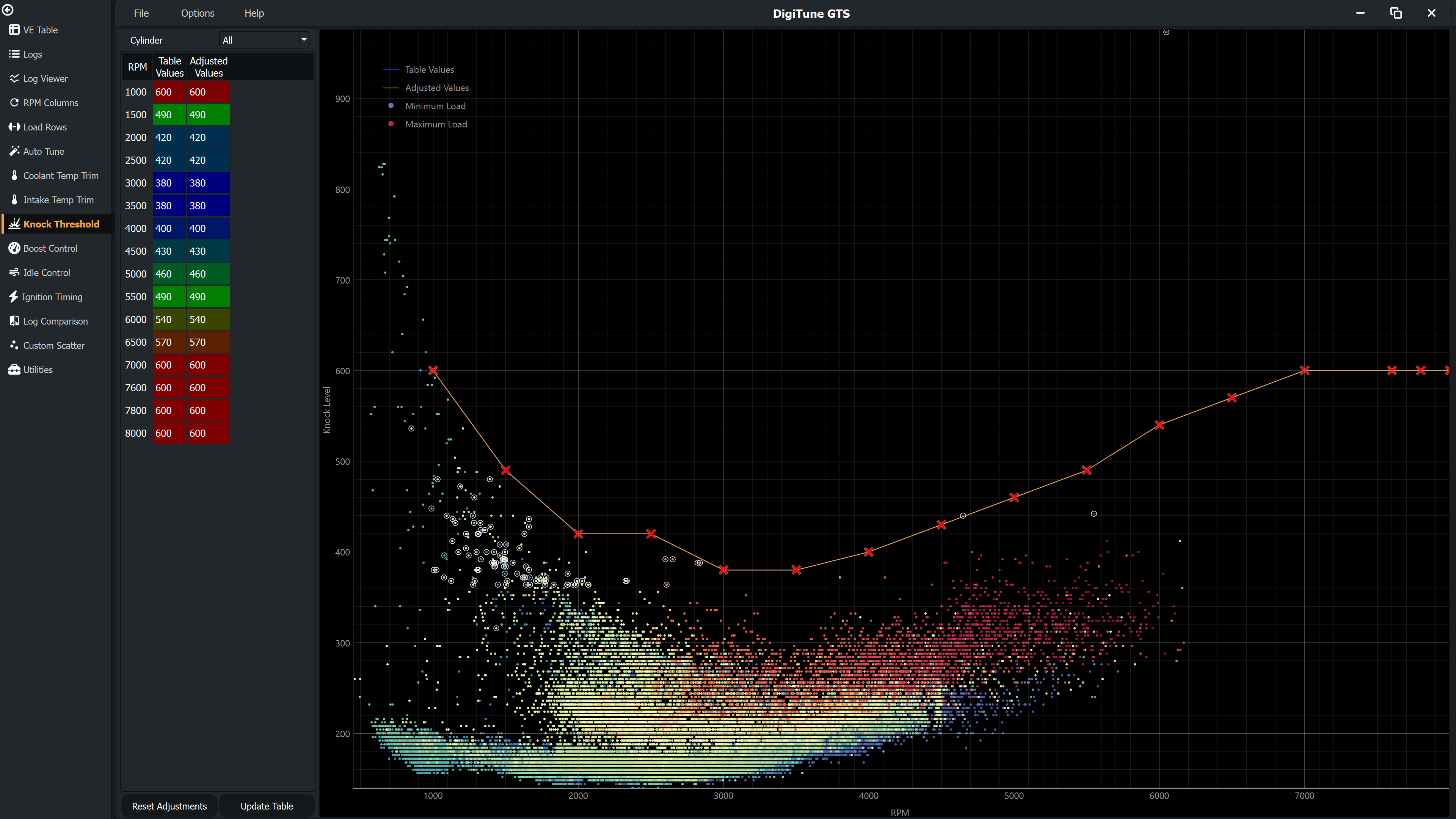
The Knock page displays logged knock sensor level data and lets you set the knock acceptable level thresholds in your ECU map. The threshold defines the level above which the ECU considers knock to be occurring. Setting it too low causes false knock events and unnecessary timing retard; setting it too high allows real knock to go undetected.
2D vs 3D knock tables
Some ECUs (notably Haltech) use a 3D knock table with both RPM and Load (TPS) axes. Others use a simpler 2D table with RPM only.
- 3D knock (Haltech) — A TPS column dropdown appears. Select a TPS breakpoint to view the knock threshold slice for that throttle position.
- 2D knock (ME, MegaSquirt) — No column selector. A cylinder dropdown lets you view data for a specific cylinder (1–4) or all cylinders combined.
How to set thresholds
- Collect a log that includes data at normal operating conditions — not during any detonation events.
- On the Knock page, observe the scatter of knock sensor readings across the RPM range. Green points represent good steady-state data.
- The threshold should sit above the noise floor of the knock sensor (the scatter at normal operation) but below the level expected during actual knock.
- Adjust the threshold values in the table. A common starting approach is to set each cell to approximately 1.3–1.5× the peak noise level observed at that RPM.
- Click Update to commit, then save and reload the map to the ECU to verify.
Setting thresholds automatically
Click Auto to have GTS suggest the whole curve from your logs. It measures the background noise level at each RPM breakpoint and places the threshold a margin above it, so random noise never trips the threshold but genuine knock still stands out. The suggestion goes into the Adjusted Values column for you to review — click Update to commit it, or Reset to discard.
Because knock sensor noise usually rises with load, each RPM breakpoint is examined at several load levels and the noisiest one sets that breakpoint's threshold. That stops a threshold based mostly on idle and cruise data from being crossed constantly during full-load pulls.
These readings are deliberately ignored, because they are not representative background noise:
- Knock events — readings the ECU flagged as knock, plus anything either side of them, so real detonation never raises the threshold that is meant to catch it.
- Isolated spikes — occasional large readings the ECU did not flag are treated as knock rather than noise.
- Engine protection cuts — overboost protection and rev limiter / launch / flat-shift cuts, plus the recovery period afterwards. The misfire from a cut is heard by the knock sensor as noise.
- Lost sync and injector max duty events — mis-timed ignition and lean misfire both excite the sensor.
- Warm-up and transient data — the same red, low-confidence data excluded elsewhere in GTS.
RPM breakpoints with too little data to judge are interpolated from their neighbours. Beyond the RPM range your log covers, the trend of the nearest calculated breakpoints is extended. The noise floor keeps climbing with RPM, so above your logged range the trend is never extended downward — a falling trend at the top of the data is treated as sampling scatter and the last calculated value is held instead. Below the logged range the trend may descend, but never further below the nearest measured noise level than the margin allows.
The curve is then lightly smoothed. Which samples happen to land in each RPM bin varies, so a single breakpoint often sits a few percent below its neighbours for no physical reason — the underlying noise floor rises fairly smoothly with RPM. Smoothing is only ever allowed to spend the margin: a value is never pulled below the noise actually measured at that RPM, because a threshold under the recorded noise would trip on noise alone. Set Auto Threshold Smoothing to 0 in Settings to turn it off and use the raw per-breakpoint figures.
A gentle spline is then fitted through the whole curve. The smoothing above compares each breakpoint with its two neighbours only, so it cannot tell that the run of breakpoints it is comparing against is itself bent; the spline is fitted to the curve as a whole and is what takes those bends out. Breakpoints your log actually measured hold their value against it — the ones that were interpolated or extrapolated in give way first — and the same rule applies as above: it may spend the margin and nothing more. Auto Threshold Curve Smoothing in Settings controls it, and 0 turns it off.
The margin defaults to 20%, adjustable in Settings under Knock along with the minimum number of samples a breakpoint needs. Treat the result as a well-informed starting point, not a substitute for verifying on a rolling road.
Editing the table
Knock threshold values are integers (no decimal places). Select cells and use the same increment/decrement and set-value shortcuts as on other tuning pages. See Keyboard Shortcuts.